

Have you noticed on some MakerWorld listings there is a little pencil and ruler icon? That means the model is customisable.
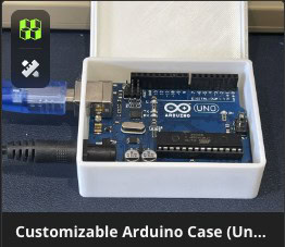
When you press the customize button, the site opens a panel of sliders and dropdowns, you change some numbers, and it delivers an STL built to your specific settings.
I looked into how it works, because I wanted to publish an electronics enclosure case/project box so you can pick your microcontroller board from a list and the mounting holes are printed in the right places.
That turned out to be a good excuse to finally learn OpenSCAD properly.
Here is what I built, what OpenSCAD does for you if you’ve never tried it, and the specific things that wasted my time so they do not waste yours.
Why make a Customiser?
First, other than the cool/nerd factor, why bother? After all, parametric is a core part of tools such as Onshape and Fusion 360, right?
In the past I played with customisers on Thingiverse just because it was a neat thing to share with people, but there is an extra incentive at MakerWorld in that they offer reward points whenever people enjoy using it.

As I write, my profile has gained 2069 points. That is mainly through uploading my 3D models, but you can get started with a bunch just by fleshing out your profile and taking the free academy courses!
What MakerWorld is actually running
MakerWorld’s Parametric Model Maker runs OpenSCAD on their servers. You upload a .scad file as a raw model file alongside your normal STLs or 3MF, the site checks if it can parse it, and if it can then your listing gets the Customize button.
Anyone who presses that button gets taken to your parameters as a visual form. They adjust the settings and the server re-renders the model. Once they are happy they can download the result.
The person customising your model never has to install anything or understand how the model is generated, and you ship a recipe rather than the cake, so one upload covers every size and variation users might need.
OpenSCAD speed run
OpenSCAD is 3D modelling but where you write code instead of clicking and dragging a mouse. There is no sketch feature like in traditional CAD tools, instead it’s more like Tinkercad where you define primitive solids, and then combine them, but all in code.
The S stands for “Solid“, or according to some, “Scripted“. Regardless, it is a whole different way to think about 3D design.
Your code starts simple but can get super complex (useful OpenSCAD cheat sheet here), and it allows you to code up and customise models that otherwise would be hugely difficult to achieve.
Get OpenSCAD
The default place to get started is at the project homepage: http://openscad.org/
There are free downloads for Windows, Mac and Linux. In Ubuntu, it is as simple as
sudo apt-get install openscad
OpenSCAD in your web browser
Using Chrome or Firefox with WebGL, you can also use OpenSCAD right in your web browser.
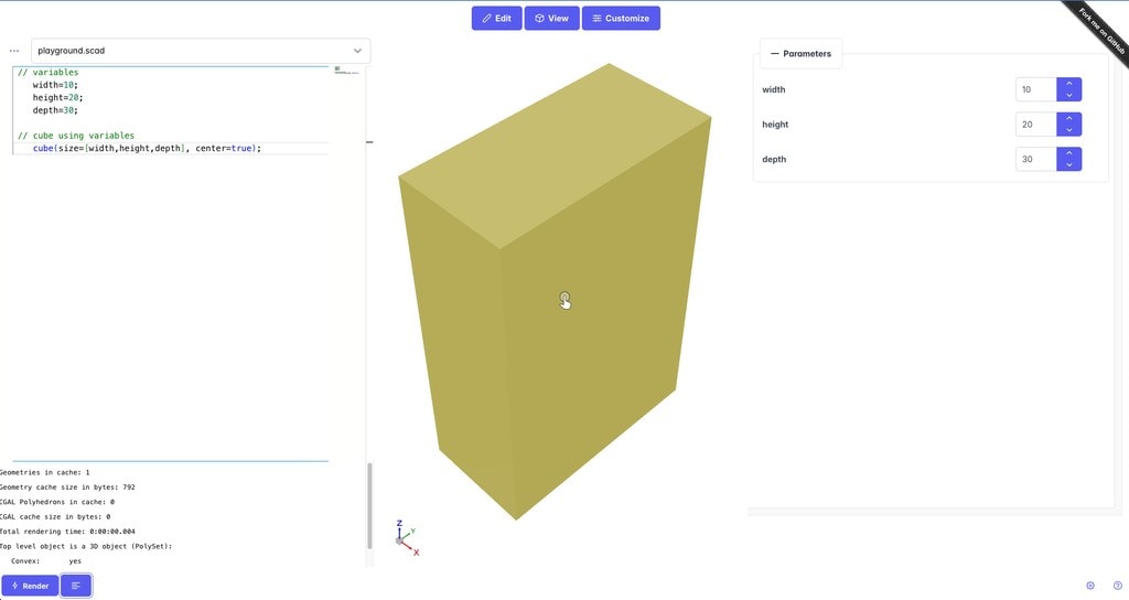
Watch the address though. openjscad.org is a dead domain now, JSCAD moved to openjscad.xyz, and openscad.net is parked and forwards you wherever pays that day.
Let’s take a look at some simple OpenSCAD code …
To add a simple cube to your workspace, you would enter:
cube(size=10, center=true);
and a sphere is similar, with radius as the sizing:
sphere(10);
center allows you to, well, centre the object.
You can also use variables (it is, after all, parametric modelling to the extreme):
 // variables
    width=10;
    height=20;
    depth=30;

 // cube using variables
    cube(size=[width,height,depth], center=true);
Transformation
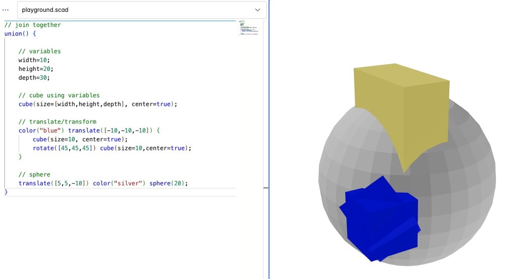
You can specify a colour:
color("black");
and translate, which shifts the position:
translate([5,5,-10])
Rotate obviously rotates, specifying the degrees for x, y and z:
rotate([45,45,45])
Boolean Operations
There are three boolean or combining operations and you can build almost anything with them. union() adds shapes together, difference() subtracts one shape from another shape, and intersection() keeps only the overlapping pieces.
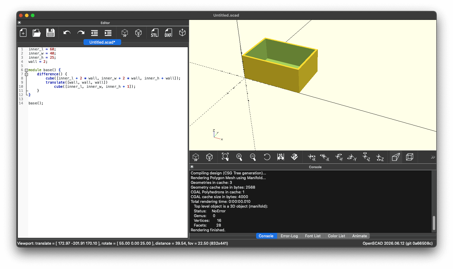
A hollow box, therefore, is simply a cube with a smaller cube subtracted from it.
Here is a working box. Paste it into OpenSCAD and press F5 or click Preview:
inner_l = 60;
inner_w = 40;
inner_h = 25;
wall = 2;

module base() {
    difference() {
        cube([inner_l + 2 * wall, inner_w + 2 * wall, inner_h + wall]);
        translate([wall, wall, wall])
            cube([inner_l, inner_w, inner_h + 1]);
    }
}

base();
The outer cube is the block of material. The inner cube, is translated (moved) in by one wall thickness, to form the hole. difference() deletes space in the first cube. The + 1 on the inner height pushes the cutting shape out through the top so the two surfaces are not exactly coincident, it stops the renderer producing a zero thickness face that it can’t figure out.
module is just a named block of geometry you can call more than once. You notice that we have named our object base() and then call it at the end. That makes our object reusable like it is one of the built-in primitives:
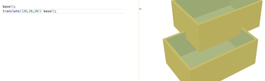
Variables at the top are our parameters that can then be tweaked. Which leads us to customisation …
How to convert an OpenSCAD script into a MakerWorld ‘Customizer’
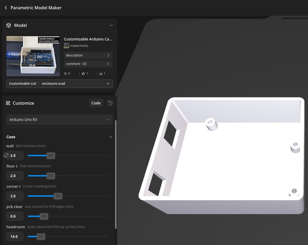
Converting your script into a customiser is easier than you would expect. OpenSCAD simply needs special comments after your variables to build a form out of them:
/* [Box] */
// Inside length (mm)
inner_l = 60;   // [20:1:150]
// Wall thickness (mm)
wall = 2;       // [1.2:0.2:4]

/* [Output] */
part = "both";  // [both, base, lid]
The [Box] line starts a named section, which becomes a collapsible group. A comment directly above a variable becomes its help text. And the comment after the value is the widget/control.
[20:1:150] is a slider from 20 to 150 in steps of 1, and a plain list like [both, base, lid] becomes a dropdown.
That is their entire API. Write sensible variables, annotate them, and the form builds itself. Everything below your variables is geometry that depends on them.
MakerWorld also ships a sample file that documents every widget the Parametric Model Maker supports, and it is the closest thing to real documentation for what the Customizer accepts. In the editor, click code, then the </> button, and Continue loads their annotated example. It replaces whatever is in the editor, so do not do that over work you have not saved.
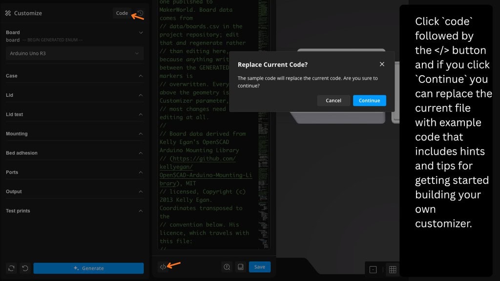
One small thing that matters if you ever write instructions for your own model: the form displays variable names with the underscores turned into spaces. fit_clear appears as “fit clear”. Tell someone to look for the underscored version and they will hunt for a label that is not on screen.
Test the form before you upload
You do not have to publish anything to find out whether your annotations worked. The browser version linked above has a Customize tab sat next to Edit and View. Paste your script in, switch to Customize, and the Parameters panel builds itself from the same comments MakerWorld reads.
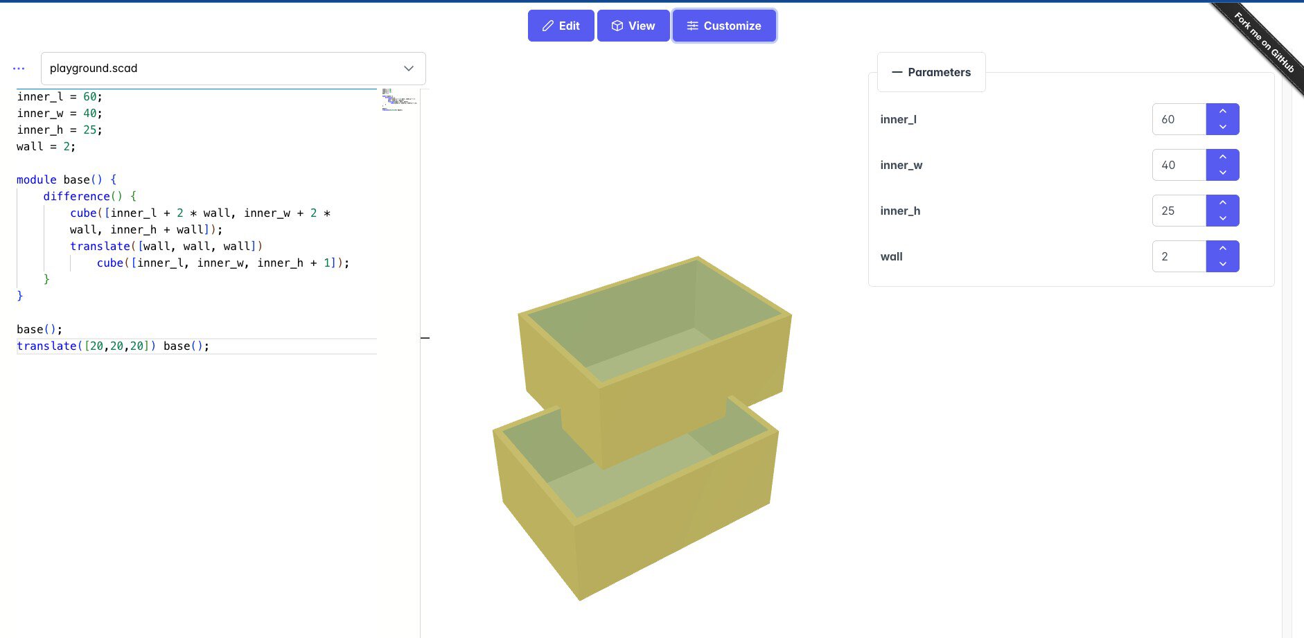
Without any annotations you still get a plain list of your variables with number boxes, which is a reasonable sanity check on its own.
Add the annotations and the panel picks them up. /* [Box] */ becomes the collapsible group, and the comment above a variable becomes its help text under the name.
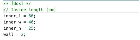
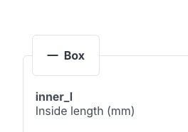
Notice the label there is inner_l, underscore and all, where MakerWorld would show it as “inner l”. Same file, two different labels, which is worth remembering when you write your instructions.
Do not treat the playground as gospel, mind. It is running its own parser, not MakerWorld’s, so it will happily accept things the real thing mangles. My colon dropdown looked perfect everywhere except where it counted.
What I built
My first customiser is the 3D printed electronics project enclosure I mentioned above, starting out as an Arduino Uno case and building from there.
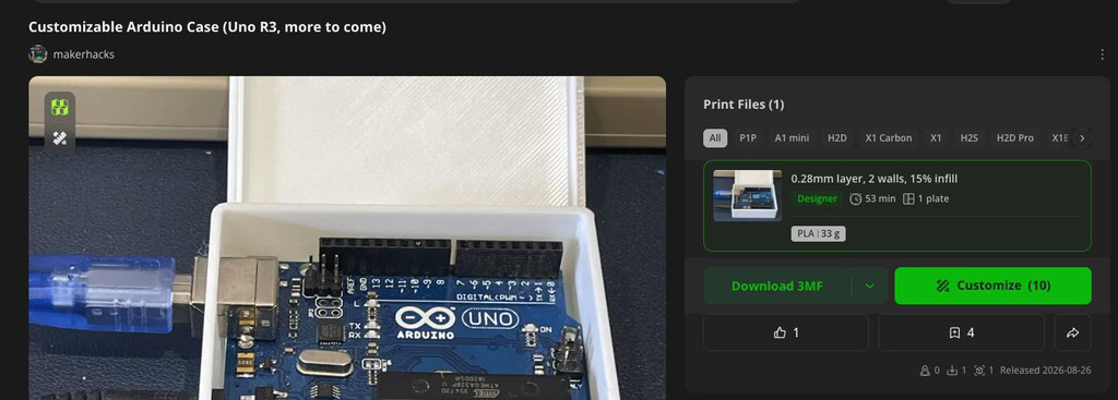
The most interesting part is not the box itself but the board measurements as parameters (PCB size, mounting hole positions, standoffs) and where the USB and power connectors are located so the openings are printed in the right places.
The geometry is deliberately simple. Each cutout is a plain box in board coordinates and subtracted generically, so now adding a second board is a row of numbers rather than designing any new models.
I say that, but when I first published this the table had exactly one row in it. The measurements came from Kelly Egan’s Arduino Mounting Library, then got checked against a real knock-off board with calipers and a bunch of test prints. That verification is the important work. Wrong hole positions turn into angry comments rather than happy makers.
Update, 25 September 2026: the table now has a second row, the Raspberry Pi 5. Same process as the Uno: take the measurements, then test print against a real board until the mounting holes, the port cutouts and the lid openings all line up.
Six important discoveries
1: The Customizer only reads the file you upload
If you tidy your board data into a second file and pull it in with include, the parameters vanish with no warning. The dropdown is simply not there.
2: minkowski() times out on their renderer
minkowski() is the usual way to make a plain box come out with nice rounded corners. While it looks lovely on your own machine, it won’t work on MakerWorld. It seems to time-out on their renderer, at least every time I have tried.
3: Your model appears wherever you modelled it
I built everything outwards from the origin, which is convenient, but the customiser drops it in the corner of the virtual print bed.
4: Decide which face should print flat on the bed
My lid prints upside down so the lip does not need supports, which means the top of the lid needs to be touching the build plate. Get this wrong and some folks might get bad results by trusting the download.
5: Check font availability
text() uses whatever fonts MakerWorld supply. A plain sans works as a default but check the currently listed fonts before assuming. You can also hand the choice over: put //font after a variable and your users get a font picker instead of a text box.
6: 3MF export looks empty
When you export from a MakerWorld customiser you can output an STL or a 3MF. I opened the 3MF, looked inside, found no mesh, and assumed the export was broken.
Turns out the 3MF format has an extension that lets a file split its geometry into separate parts, so the main file holds a pointer to the actual triangles which live in 3D/Objects/object_1.model.
Try it yourself
Install OpenSCAD or go visit one of the browser based versions, paste the examples above.
If you make something and want it on MakerWorld, upload your .scad under Raw Model Files when you publish. It will say Validating and then Passed, and the Customize button turns up on your listing.
Passing only means it passed their automation, though. Mine passed with a design that would not have printed first time, so press the button yourself and try every option before you tell anyone about it!
The case is Customizable Arduino Uno & Raspberry Pi 5 Case if you want to poke at the parameters. Two boards so far, the Uno R3 and the Raspberry Pi 5. If there is one you want adding next, say which and I will source a real board to measure.
And if you do print one, leave a comment or a rating on the listing. It tells me the parameters survived contact with someone else’s printer, which is the only real test, and it is a good chunk of what MakerWorld uses to decide whether to show a model to anyone else.

 xTool M2 Review: Print and Laser Cut in One Machine (?)