
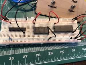
Z80 CPU running on a breadboard? – how very 1970s!
Creating a “Homebrew Computer” using the Zilog Z80 processor is a right of passage for a certain segment of nerds of a certain age, but since Ben Eater started his series on his 6502 breadboard computer a lot more interest has been generated in the whole DIY computer area.
In this video I present a variation on the most simple “test circuit”, just enough to ensure the chip actually works (many Z80 chips are actually recovered from recycled machines from the 1980s, and there are even clones sold online!).
To my shame, this video was meant to be the start of a series. Unfortunately I dropped the ball when our family had its life turned upside down (like many families out there over the last few years).
It’s time to return to this and see it through to the end for you all!
Homebrew Z80 Computer Options
There are a few options for getting a minimal homebrew Z80 working, ranging from the absolutely bare-bones hardcore “as they would have done it in the 70s” to much more convenient options, even some that don’t actually use real Z80 hardware.

In this series I will share my experience with several of them, and over on Retro Game Coders we will code up some programs and see how things are different, but I wanted to start with the setup I think most hardware fans will want to at least check out – The breadboard z80.
Breadboard Z80 with Arduino Clock
After I published the video above, I continued the project making an actual ‘useful’ retro computing machine, and I was able to program it in machine code, running from ROM. I laser cut a “front panel” with switches allowing full auto or instruction stepping, using programmable logic for address decoding etc.
All of this has gone astray during our move from Canada back to England so I need to recreate it.

I will share full schematics incrementally as I return to the experiment and rebuild.
Z80 Pin Diagram
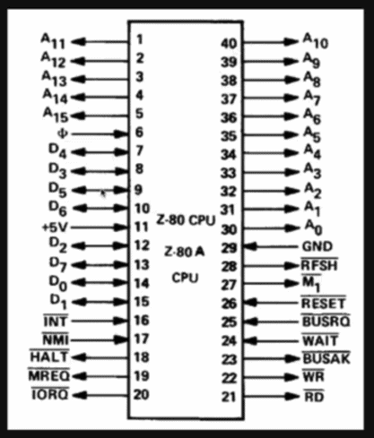
- A0-15: Address lines
- CLK: Clock (rising edge trigger)
- D0-D7: Data lines
- +5V: Power
- INT: Interrupt request
- NMI: Non-maskable interrupt request
- HALT (active low)
- MREQ: Memory request (active low)
- IORQ: IO request (active low)
- REFSH: Refresh timing (active low)
- MI: Maskable interrupt request (active low)
- BUSRQ: Bus request
- BUSAK: Bus acknowledgement (active low)
- WR: Write (active low)
- RD: Read (active low)
Symbols with the line over are active low but can be represented in many ways including / or ! in some diagrams.
Minimal Z80 Test Circuit
A Z80 will start running when supplied 5V and if reset is held low. It will look for the first operation instruction at Address 0000.
Here is what you need for just the minimal circuit to power up and see that it is operational:
- 5v power and Clock (in my case, supplied by Arduino Uno – see code below)
- Data lines held low (AKA NOP, or ‘no operation’)
- Address lines connected to LEDs via resistors (not something you should do long-term as the z80 is not rated to supply much current via the pins)
- Control lines set (see below).

Hooking up the “Test” circuit

- Insert the Z80 and connect the Arduino Ground and 5v. Connect your breadboard power and ground rails.
- Connect the INT, NMI, BUSRQ, and WAIT on the Z80 to 5V, these are activated when held low.
- Connect the data lines (D0 to D7) to ground.
- Connect Reset to 5v.
- Connect LEDs to resistors and the address lines. I am using 1k resistors to limit the current on these fragile pins.
- Connect Clock (pin 6) to the Arduino pin 5. Optionally also connect an LED and resistor.

Arduino Clock Code
Rather than use a crystal or even a 555 chip, my project uses an Arduino to control the clock. This has a lot of convenience, especially if later you want to mimic a ROM chip using the Arduino memory, but does have timing and speed challenges due to the way Arduino code works and the little 8 bit processors on them.
Connect the Z80 “Clock” pin and optionally, an LED on Pin 5.
Previously I used a library that allowed the Arduino to “multitask” called Eventually, but we are running at such slow speeds for these tests it was unnecessary, so here is the simpler code.
On start, the Z80 is reset using a wire on Pin 9, and then the Arduino will keep pulsing the clock on pin 5 with a delay of whatever you choose in the setting int speed = 500;
#define CLOCKLED 5
#define RESET_PIN 9

// Initialize the speed
int speed = 500;
int steps = 0;

void sleep(int sleep_time)
{
  long start_time = millis();

  while(millis() < start_time + sleep_time)
  {
    // do nothing
  }
}

// Tick the clock
void toggle_clock()
{
  digitalWrite(CLOCKLED, HIGH);
  sleep(10);
  digitalWrite(CLOCKLED, LOW);
  sleep(10);
}


void setup() {

  // set up the pins and the event listeners
  pinMode(CLOCKLED, OUTPUT);
  pinMode(RESET_PIN, OUTPUT);

  // initialize serial communication
  Serial.begin(115200);

   // Reset the computer
  Serial.println("STARTING ...");
  digitalWrite(RESET_PIN, LOW);
  sleep(5000);
  toggle_clock();
  sleep(speed);
  toggle_clock();
  sleep(speed);
  toggle_clock();
  sleep(speed);
  toggle_clock();
  sleep(speed);
  digitalWrite(RESET_PIN, HIGH);
  Serial.println("STARTED");

}

void loop()
{
  sleep(speed);
  toggle_clock();
}
Next Steps
Currently we can see something is happening because we have LEDs on the address lines, but that only means the chip is looking to the bus. Really we should have more indicators to tell us what exactly is happening at each stage.
Even better, rather than just count up addresses we will want to do some actual instructions. For this we will need to hook up a button so we can step to the next program instruction, and we will need some ROM or RAM to store those instructions.
Check out Part 2 now.
Beyond the Z80


As well as the Z80, I also plan on using a 6502 processor, which was the chip family most-famously powering the Commodore Vic 20, C64, Atari, Apple II, and BBC microcomputers!
Like many people, I particularly enjoy Ben Eater’s videos, and despite already having everything I need, and have made a 6502 board before (not as good as his of course), I bought his kit to support his endeavours and encourage him to keep making great YouTubes!
If you want to dig into all the information around the z80 and how to get it running before my tutorials, or in addition to, there is an excellent resource at http://z80.info/
Another famously useful resource is Grant’s at http://www.searle.wales/
Please share if you have other recommendations, feedback, or ideas!

 Makeblock mBot Ranger Robotics Kit Review