
You need a Raspberry Pi Pico for this one, and Pimoroni is where I buy mine. That is an affiliate link, so I get a few percent if you use it, at no extra cost to you.
Building Z80 computers starts with power and some signal lines, and as we previously saw in DIY Z80 part 1, you can see some LEDs blinking to prove that it is working.
If you want your homebrew computer to do actual computing, however, you need to add memory, so that is what we will look at next.
Important: Get a CMOS Z80
Single stepping, and even going down to the lowest speeds, likely means you need a more modern and robust Z80. Yeah “modern Z80” isn’t something you hear a lot, but there are some features of the CMOS versions of the Z80 that allow us to abuse them and get away with it.
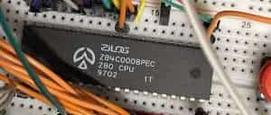
A CMOS Z80 can run from zero to its advertised data sheet speed, you can tell you have one of these guys because it has the letter “C” in the beginning of the part number, eg. Z84C0020PEC:

Looks like my CMOS chip here is relatively recent too, I think that 1240 means “40th week of 2012”? Which means the NMOS chip above is from 1987 which seems about the right vintage.
Don’t confuse the end of the part where it says PSC or PEC, those with PEC indicate “industrial” versions of the chips with better temperature ranges (-40°C to 100°C) than the regular consumer version.
The NMOS Z80 will still be useful, and will likely be cheaper if you find a reliable e-waste supplier or specialist, but we can’t run it slowly or stall it for single-stepping, it can only run at its intended speed, e.g. 4MHz.
Personally, if I have to choose, I would go for price and reliability over MHZ for these projects as they won’t be running anywhere near the speeds they are capable of.
Testing all the Z80 connections
Before we get to the ROM and RAM, we should make sure we have a full understanding of how everything should work.
Here is my breadboard at this point, with a Pico now instead of the Arduino. Note we have a potentiometer attached to allow us to dial in the clock speed, but that is not really necessary.
The most important clock improvement is being able to choose to manually single-step through as well as leave the computer running automatically.
Only 4 address lines are shown, but of course adding the others is a simple matter of adding more resistors and lines.

Now we need to look at the Pico (or Arduino) pin connections:

- AUTO is the trim pot data line, we connect that to the analog pin: A0
- CLOCK and LED Pin GP5
- Step BUTTON is Pin GP7
- RESET line to the Z80 is Pin GP9
If you recall from last time, the Z80 resets if we hold the reset pin low whereas the clock pin (Pin 6 on the Z80) just needs a pulse to let it know to go to the next instruction. We can optionally also hold WAIT low which literally tells the CPU to wait.
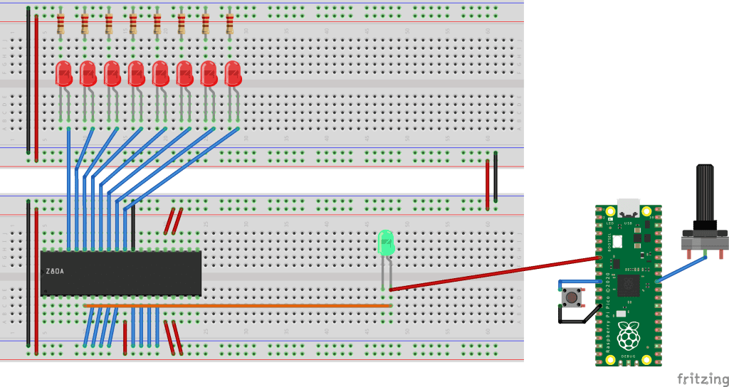
To see what is going on with the computer we can add LEDs. Address lines are active HIGH so we just need LEDs and resistors as normal, with the line going to the positive (Anode) and the negative (Cathode, short leg with the flat side of the LED bulb) connected to ground.
For signals, however, they are active LOW therefore we want them to light up in reverse of the usual arrangement. Here I have set up both types on a breadboard to hopefully make it clear:

Notice how the LED on the left has the signal on one leg, the Cathode or -, and the other leg, the Anode, is connected to the 5v rail.
You can tell the LED on the right has the Cathode connected to Ground because it is the side of the LED with the flat part of the red bulb.
I chose to connect up the Read, Write and Memory Request lines, switching to the IO Request once I had reassured myself that everything was operating as it should.
Variable Speed Control and Single-Stepping the Z80 Arduino Code
Conveniently, the Raspberry Pi Pico can make use of the Arduino code by adding the board definition file in a similar way that we can program ESP32 boards.
#define AUTO  A0
#define CLOCKLED 5
#define BUTTON_PIN 7
#define RESET_PIN 9

// Initialize the speed to OFF
int speed = 0;
int oldSpeed = 0;
int steps = 0;

void sleep(int sleep_time)
{
  long start_time = millis();

  while(millis() < start_time + sleep_time)
  {
    // do nothing
  }
}

// Tick the clock
void toggle_clock()
{
  digitalWrite(CLOCKLED, HIGH);
  sleep(10);
  digitalWrite(CLOCKLED, LOW);
  sleep(10);
}

// Single increment of the clock
void single_step()
{
  toggle_clock();
  Serial.print("STEP ");
  Serial.println(steps);
  steps++;
  sleep(500);
}


void setup() {

  // set up the pins and the event listeners
  pinMode(CLOCKLED, OUTPUT);
  pinMode(BUTTON_PIN, INPUT);
  pinMode(RESET_PIN, OUTPUT);
  pinMode(AUTO, INPUT);

  // initialize serial communication
  Serial.begin(115200);

   // Reset the computer
  Serial.println("STARTING ...");
  digitalWrite(RESET_PIN, LOW);
  sleep(5000);
  single_step();
  single_step();
  single_step();
  single_step();
  digitalWrite(RESET_PIN, HIGH);
  Serial.println("STARTED");

}

void loop()
{

  // What is the pot set to?
  speed = analogRead(AUTO);

  if(abs(speed-oldSpeed)>30) {

    oldSpeed = speed;

    if(speed > 1000)
    {
      // Manual stepping listener
      Serial.println("AUTO OFF");

    }
    else
    {
      // Set the speed to the trim pot
      Serial.print("POT: ");
      Serial.println(speed);
    }

  }
  else
  {

      if(speed > 1000) {
        if(digitalRead(BUTTON_PIN))
        {
          single_step();
        }
      } else {
        sleep(speed);
        toggle_clock();
      }
  }
}
Two Picos and back to one Pico
Sadly, once I started adding even more wires, and another breadboard, signal and stability failures became a real pain (just a slide nudge of one of the components would make intermittent errors), but at one point I did manage to have one Pico as the clock and as an automatic reset circuit, and another Pico as the ROM and RAM.
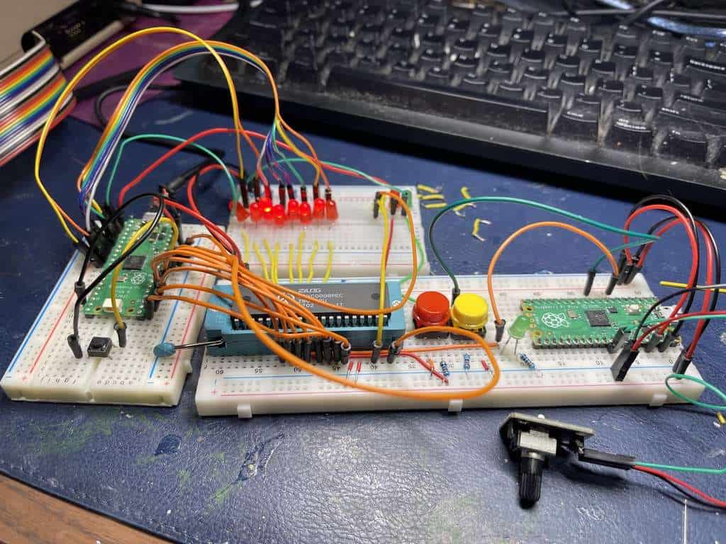
With protoboard or PCBs you would not have those issues, but I chose to simplify down to one Pico and the Z80 after proving it could work!

For my convenience more than anything, seeing as there was a lot of editing and testing, I switched to Micropython which is interpreted and therefore allows me to test and hack the code in more of a realtime way.
Emulating Z80 ROM/RAM
Emulating ROM and RAM memory is a simple case of setting up an array large enough to cover all the addresses that might be read from or written to.
Here is where we hit a snag going with the Pico as our microcontroller.
As well as wiring up the address and data pins, we also need those control signals. Unfortunately, the Pico just does not have enough pins to do everything so sacrifices had to be made.
While the Z80 can address 64KB of memory in total, we only have enough pins spare for 16KB, or 8KB if we need that one extra pin (eg. to hold the WAIT line).
Neither the Z80 nor the Pico care if it is ROM or RAM, and in a way it is really getting a kind of RAM that is pre-filled with up to 16KB bootstrap code.
# Fill RAM with 0 / NOP
ram_memory = []
# 8kb = 8181
# 16kb = 16382
for b in range(16382-len(ram_memory)):
    ram_memory.append(0)
Running the Program
Using something like Thonny or Visual Studio Code (use the MicroPython extensions) we can both edit our code and watch it run on the Pico via REPL. Just remember that if we run too fast then we can find it difficult to break out of the program to make changes.
On my Mac I like to use RShell for file transfer to the Pico and Minicom to monitor the serial terminal, eg.
pip3 install rshell
rshell -p /dev/tty.usbmodem1231401

brew install minicom
minicom -D /dev/tty.usbmodem1231401 -b 115200
Our clock is set using the following:
Clock_Timer.init(mode=Timer.PERIODIC, callback=clock_tick, freq=50)
Set the freq to how many times per second you want the Pico to attempt to fire. It won’t be at all exact at higher levels because as mentioned elsewhere, we are really at the mercy of the UART and MicroPython speed as much as my inefficient code!
MicroPython Code
You will notice I commented out the interrupt setup because for some reason the Z80 pulling my pins high and low was not detected by the Pico. I would love to know why!
WR.irq(handler=wr_handler, trigger=Pin.IRQ_FALLING)
RD.irq(handler=rd_handler, trigger=Pin.IRQ_FALLING)
IOREQ.irq(handler=io_handler, trigger=Pin.IRQ_FALLING)
Instead I had to use a loop and check the status of those lines, calling the handler subroutines I set up for the IRQ version.
The ANSI library I import is my own stripped down set of ANSI escape code strings to make the output prettier and easier to read but you can forgo all of that fancy formatting in your version.
Not sure if it makes a huge difference with what we are doing here, using 115200 baud serial comms after all, I overclock my Pico using
machine.freq(270000000)Yes, the Python array sets up a Z80 machine code program that outputs Hello World! to the IO. We will circle back to this later in the series, just know that we can set up a “ROM” this way, and by loading a binary file we can also change that ROM without editing the Python.
import sys
from ansi import *
import machine
from machine import Pin, Timer
from utime import sleep

# This sets the Pico to full speed
machine.freq(270000000)
print(machine.freq())

is_IO = False
is_reading = False
is_writing = False
this_address = 0
this_data = 0

# Address Pins
address = []
address_pins = [2,3,4,5,6,7,8,9,10,11,12,13,14,15]
for pin_number in address_pins:
    address.append(Pin(pin_number, Pin.IN))

# Data pins
datavalues = []
data_pins = [16,17,18,19,20,21,22,26]
for pin_number in data_pins:
    datavalues.append(Pin(pin_number, Pin.OUT))

# Write and Read signals
Clock = Pin("GP28", Pin.OUT)
Clock_Timer = Timer()
WR = Pin("GP0", Pin.IN, Pin.PULL_UP)
RD = Pin("GP1", Pin.IN, Pin.PULL_UP)

# IO Request
IOREQ = Pin(27, Pin.IN, Pin.PULL_UP)


# LED status light
led_pin = Pin("LED", Pin.OUT)

# Clock Ticks
tick = 0

# ROM/RAM
# ROM/RAM
ram_memory = [

    0x3E, 0x48,       	#LD A,48H ("H")
    0xD3, 0x0A,       	#OUT (0AH),A
    0x3E, 0x45,       	#LD A,45H ("e")
    0xD3, 0x0A,       	#OUT (0AH),A
    0x3E, 0x4C,       	#LD A,4CH
    0xD3, 0x0A,       	#OUT (0AH),A
    0x3E, 0x4C,       	#LD A,4CH
    0xD3, 0x0A,       	#OUT (0AH),A
    0x3E, 0x4F,       	#LD A,4FH
    0xD3, 0x0A,       	#OUT (0AH),A
    0x3E, 0x20,       	#LD A,20H
    0xD3, 0x0A,       	#OUT (0AH),A
    0x3E, 0x57,       	#LD A,57H
    0xD3, 0x0A,       	#OUT (0AH),A
    0x3E, 0x4F,       	#LD A,4FH
    0xD3, 0x0A,       	#OUT (0AH),A
    0x3E, 0x52,       	#LD A,52H
    0xD3, 0x0A,       	#OUT (0AH),A
    0x3E, 0x4C,       	#LD A,4CH
    0xD3, 0x0A,       	#OUT (0AH),A
    0x3E, 0x44,       	#LD A,44H
    0xD3, 0x0A,       	#OUT (0AH),A
    0x3E, 0x21,       	#LD A,21H
    0xD3, 0x0A,       	#OUT (0AH),A
    0xC3, 0x00, 0x00,  	#JP 0000
    0x76              	#HALT

]

print("Booting")

# Get the address pins
def get_address():
    global tick, is_IO, is_reading, is_writing, this_address, address, this_data, datavalues, ram_memory
    this_address = 0
    for address_pin in reversed(address):
         this_address = (this_address << 1) + address_pin.value()

    #print(this_address)
    return this_address

# Set the pins to correct values
def set_pins(pins, data):

    global tick, is_IO, is_reading, is_writing, this_address, address, this_data, datavalues, ram_memory

    for pin in pins:
        this_bit = data & 0x01
        if(this_bit == 1):
            pin.on()
        else:
            pin.off()
        data = (data >> 1)
        #print(data)

# Output the Z80 values
def print_status():
    global tick, is_IO, is_reading, is_writing, this_address, address, this_data, datavalues, ram_memory

    # Check if IO
    is_IO = (IOREQ.value()==0)

    # When RD is low then z80 is reading
    is_reading = (RD.value()==0)

    # Check if is writing
    is_writing = (WR.value()==0)

    # Get the address and the data for it
    this_address = get_address()
    this_data = ram_memory[this_address]

    #print(top)
    print('{:8}'.format(tick), end='')
    print(bold + " IO: " + reset, abs(is_IO),end='')
    print(bold + " RD: " + reset, abs(is_reading), end='')
    print(bold + " WR: " + reset, abs(is_writing), end='')
    print(bold + " Address:" + reset + " {:#018b}".format(this_address), end='')
    print(bold + " Data:" + reset + " {:#010b}".format(this_data), end='')
    print(" {:#06x}".format(this_data), reset, end='')

    if this_data < 126 and this_data >= 32:
        print(chr(this_data), end='')
    else:
        print("", end='')

    print()
    #print(clearline)


# Write handler
def wr_handler(pin):
    global tick, is_IO, is_reading, is_writing, this_address, address, this_data, datavalues, ram_memory

    # NOT IO so is writing to memory
    if(IOREQ.value()==1):
        this_address = get_address()
        # WAIT.value(0)
        for data_pin in reversed(datavalues):
            data_pin.init(mode=Pin.IN)
        for data_pin in reversed(datavalues):
            this_data = (this_data << 1) + data_pin.value()
            try:
                ram_memory[this_address] = this_data
            except:
                print("OOPS! Requested to write ", this_address)

        # WAIT.value(1)
        print_status()
        tick = tick + 1

# Read handler
def rd_handler(pin):

    global tick, is_IO, is_reading, is_writing, this_address, address, this_data, datavalues, ram_memory

    #print("IO :",IOREQ.value())

    # Not IO - Reading from memory
    if(IOREQ.value()==1):

        this_address = get_address()

        for data_pin in reversed(datavalues):
            data_pin.init(mode=Pin.OUT)


        this_data = ram_memory[this_address]
        set_pins(datavalues, this_data)

        #print(this_data)

        print_status()
        tick = tick + 1

# IO Handler
def io_handler(pin):

    global tick, is_IO, is_reading, is_writing, this_address, address, this_data, datavalues, ram_memory
    print_status()
    tick = tick + 1

# Handle clock ticks
def clock_tick(timer):

    global tick
    led_pin.value(1)
    Clock.toggle()
    sleep(0.1)
    led_pin.value(0)
    tick = tick + 1
    if(RD.value()==0): rd_handler(RD)
    if(WR.value()==0): wr_handler(WR)
    if(IOREQ.value()==0): io_handler(IOREQ)

# Fill rest of the 8kb with NOP
# 8kb = 8181
# 16kb = 16382
for b in range(16382-len(ram_memory)):
    ram_memory.append(0)

# Interupts
# WR.irq(handler=wr_handler, trigger=Pin.IRQ_FALLING)
# RD.irq(handler=rd_handler, trigger=Pin.IRQ_FALLING)
# IOREQ.irq(handler=io_handler, trigger=Pin.IRQ_FALLING)

# Wait
#WAIT = Pin("GP15", Pin.OUT)
#WAIT.LOW()

# Boot up procedure
print("Memory: ", len(ram_memory))

# Read "ROM" data as binary into memory array
#with open("z80.bin", mode='rb') as file:
#    ram_memory = bytearray(file.read())


# Clock input
Clock_Timer.init(mode=Timer.PERIODIC, callback=clock_tick, freq=1000)
Next Steps
Right now we can see the Z80 attempt to output Hello World! by watching the memory and control signals, but we can’t see the result of that in reality because we don’t actually have any IO on our computer! Let’s set that right in the next instalment.

 Z80 on a Breadboard: Homebrew Retro Computer Part 1