

Arduino, Raspberry Pi, Pico and ESP32 projects very often run out of GPIO pins, and that can be frustrating and limiting.
You could upgrade to a more expensive board that offers more IO, such as an Arduino Mega. There are ways to use shift registers too.
Alternatively, you can use “polling” techniques, where you scan rows and columns really quickly, which we will look at in a future project where I build my own dream hand-wired mechanical keyboard.
Instead, today I am going to show how you can use a port expander like the MCP23008 or MCP23017.
Why use MCP23008 or MCP23017?
The great advantage to using MCP23008 or MCP23017 is they work using I2C, and that means you only lose two pins to gain 8 or 16 GPIO, depending on the chip you buy.
Even better, because I2C can be daisy chained, you can have a whole bunch of these chips – up to 8, with unique addresses. That makes 128 I/O pins!
Not only can you add IO, but each pin can have an internal pull-up resistor, meaning fewer components, and there are interrupts so you don’t have to keep checking the inputs to see if they have changed.
You can use these chips with 3.3V or 5V devices, so it is a great, small, and inexpensive option for most of the projects you might come across.
As well as expanding your IO, it also protects your sensitive electronics – it can handle drawing around 20mA on each pin – and if it does fry, it is a lot cheaper to replace than some of our vintage and/or fragile computers.
They come as bare chips, as I have here, or many companies produce break-out boards and shields to make it even more convenient for prototyping.
More info is available at the official datasheet.
MCP23017 Pins and Wiring up to Arduino

The MCP23017 and MCP23008 are pretty similar except the MCP23017 has 16 IO pins, while the 08 has 8.
Confusingly, the power and ground are usually labelled as VDD (Power) and VSS (Ground) so I amended the diagram here to make it clearer.
The next two important pins are SCK and SDA, which are the I2C communication lines. They need to connect to your microcontroller I2C pins, for example A4 and A5 on the Arduino Uno.
There are three Address pins, A0, A1, A2, which are set high or low to configure the I2C address of the chip. Connecting all three to ground makes the address Hex 0x20.
Finally, the Reset pin needs to be held high (connect to 5v, for example) because it is activated when low.

Yeah using all this wiring to blink one LED seems a bit of a waste of time, but once you have one pin working it is super easy to then use the other 15!
If you are using Arduino, the best option is to add the Adafruit MCP23X17 library and use it like so:
#include <Adafruit_MCP23X17.h>
#define LED_PIN 8     // MCP23XXX pin LED is attached to

Adafruit_MCP23X17 mcp;

void setup() {

  // Wait for connection
  if (!mcp.begin_I2C()) {
    while (1);
  }

  // configure chosen pin as output
  mcp.pinMode(LED_PIN, OUTPUT);

}

void loop() {
  mcp.digitalWrite(LED_PIN, HIGH);
  delay(500);
  mcp.digitalWrite(LED_PIN, LOW);
  delay(500);
}
Using MCP23017 with Raspberry Pi Pico and MicroPython
If you don’t have ready access to a third-party library, never fear because controlling the chip and reading the inputs is done pretty simply via I2C registers.
On the MCP23017, there are two “banks” of pins. Those on the right are Bank A and those on the left are Bank B.
Each bank are addressed using registers to set which pins you wish to make input, which to make output, and which pins need pull-up resistors.
First we will look at MicroPython on the Pico:
from time import sleep
import machine

i2c = machine.I2C(0,
                  scl=machine.Pin(17),
                  sda=machine.Pin(16),)
i2cdevices = i2c.scan()
print(i2cdevices)
sleep(0.50)


i2c.writeto_mem(0x20, 0x00, b'\xFF')
i2c.writeto_mem(0x20, 0x01, b'\x00')
i2c.writeto_mem(0x20, 0x13, b'\x00')

while(1):

    i2c.writeto_mem(0x20, 0x13, b'\xFF')
    sleep(0.50)
    i2c.writeto_mem(0x20, 0x13, b'\x00')
    sleep(0.50)
As you can see, we have:
SCL on Pin 17
SDA on Pin 16
Power is 3v, and we also need Ground

We can see if our device is visible with the i2c.scan() which returns a list of I2C devices that have been detected, albeit using a brute-force method so don’t rely on it too much.
Our chip has been set to be 0x20, however, so we can write to that device and the relevant registers like this:
# Bank A
i2c.writeto_mem(0x20, 0x00, b'\xFF')
# Bank B
i2c.writeto_mem(0x20, 0x01, b'\x00')
Here we say we want Bank A (Hex 0) to be all inputs (hex FF), all Bank B (Hex 01) to be outputs (all 0). We turn the Led on and off using:
# All Bank B HIGH
i2c.writeto_mem(0x20, 0x13, b'\xFF')
# All Bank B LOW
i2c.writeto_mem(0x20, 0x13, b'\x00')
For input it is only slightly different, we just read from register 12, but we do set the pull-up resisters to be on, using register 0x0C:
from time import sleep
import machine

i2c = machine.I2C(0,
                  scl=machine.Pin(17),
                  sda=machine.Pin(16),)

i2c.writeto_mem(0x20, 0x00, b'\xFF')
i2c.writeto_mem(0x20, 0x01, b'\x00')
i2c.writeto_mem(0x20, 0x0C, b'\xFF')
i2c.writeto_mem(0x20, 0x13, b'\x00')

while(1):

    button = i2c.readfrom_mem(0x20, 0x12, 1)
    print(button)

    if (button!=b'\xFF'):
        i2c.writeto_mem(0x20, 0x13, b'\xFF')
    else:
        i2c.writeto_mem(0x20, 0x13, b'\x00')
    sleep(0.10)
MCP23017 with I2C on Neo6502

Here is the same Blink setup, but with the Neo6502.
Pin 1 – 5v
Pin 2 – Gnd
Pin 4 – SCK
Pin 5 – SDA
On the Neo6502 GPIO (Neo6502 is the fantastic credit-card sized 6502 computer) we can use the BASIC iwrite instruction to send our commands to the chip, Again, we are using Hex 20 as the I2C address:
iwrite $20, $0, $FF
This would set Bank A as Inputs ($FF in hex is 255 in decimal, which in binary means each pin is 1 or “On”). To set as output we set each “Off” or zero, as here where we set Bank B as outputs:
iwrite $20, $1, $0
To read or write there are the registers $12 for Bank A and $13 for Bank B. Therefore if you want to set all of Bank B “High”, aka switch all those pins “On”, we can do:
iwrite $20, $13, $FF
As it stands, we can read from Bank A and get the result of all the pins, high or low, using:
iread($20,$12)
The problem is the result won’t change next time we read it as it will “remember” it’s value, so we need to use a pull-up. The registers for Pull-Ups are $0C and $0D as appropriate, so we set Bank A to use them like so:
iwrite $20,$C,$FF
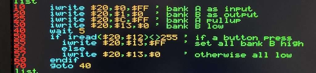
Here is a full BASIC listing for the Neo6502 using a MCP23017 to light an LED when a button is pressed:


 PiUSB – How to Make a Wifi Memory Stick Using Pi Zero W